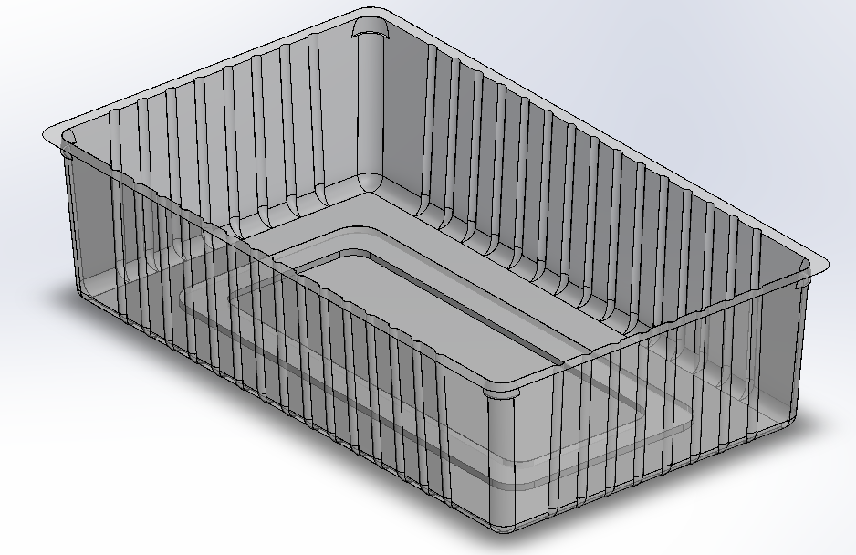
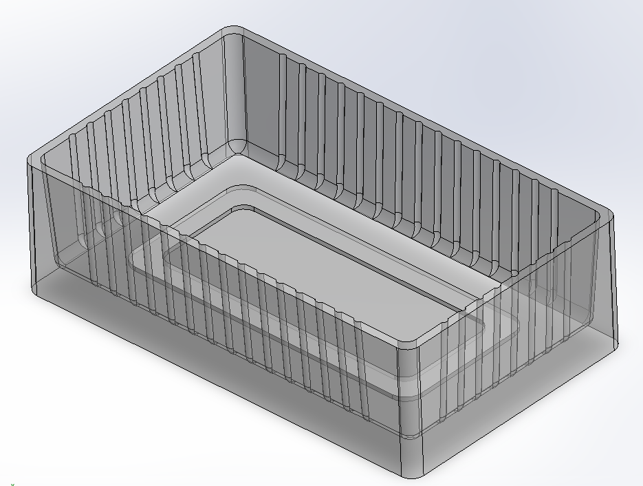
A sample cavity design replicating the vacuum forming process for industrial plastic trays. This design demonstrates key engineering considerations for mold creation.
This is a sample cavity design that replicates the design process of industrial plastic trays using the vacuum forming method. The original design is confidential, so this sample demonstrates the complete workflow and considerations required for creating functional molds.
The cavity design includes all the critical considerations needed for manufacturing, including tool constraints, material shrinkage, and stackability requirements.
Before beginning the design process, we established clear dimensional requirements and constraints that would guide every engineering decision.

Several key considerations must be addressed during the design phase to ensure manufacturability and functionality of the final product.
The tray was created through a 10 step process, each building upon the previous to achieve the final mold design.
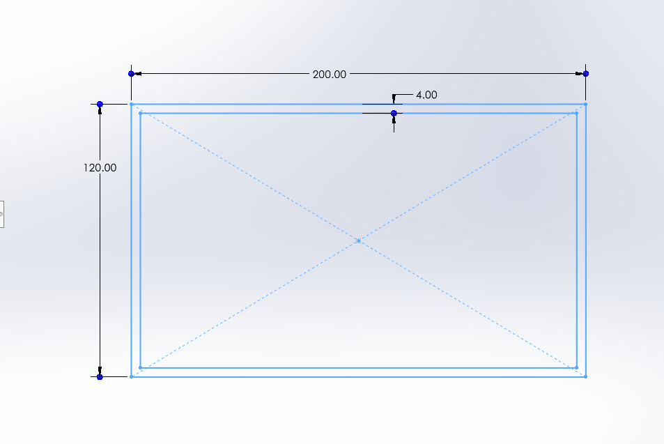
The first step was to create guideline sketches. This indicates the outer dimensions first. For this sample, we used 200mm × 120mm. A 4mm offset was set from the inner to outer section, defining the top part of the cavity.
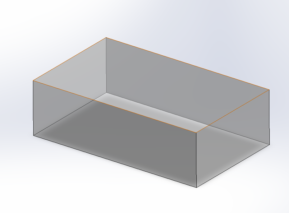
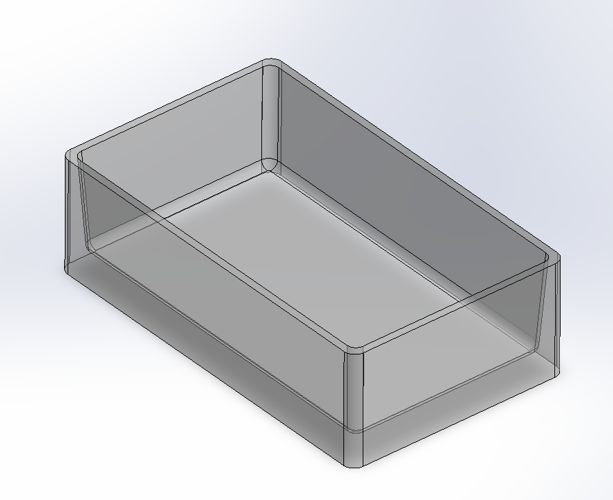
The next step was to create the actual sketches based on the guidelines and extrude them downwards. The extrusion value needed to be at least 55mm to accommodate the minimum cavity height of 50mm. We chose 60mm for added material strength.
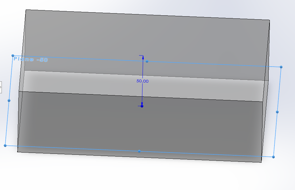
After the extrusion, I created a new plane 50mm below the original sketch. This plane defines the dimensions of the lower part of the tray and serves as the reference for subsequent operations.
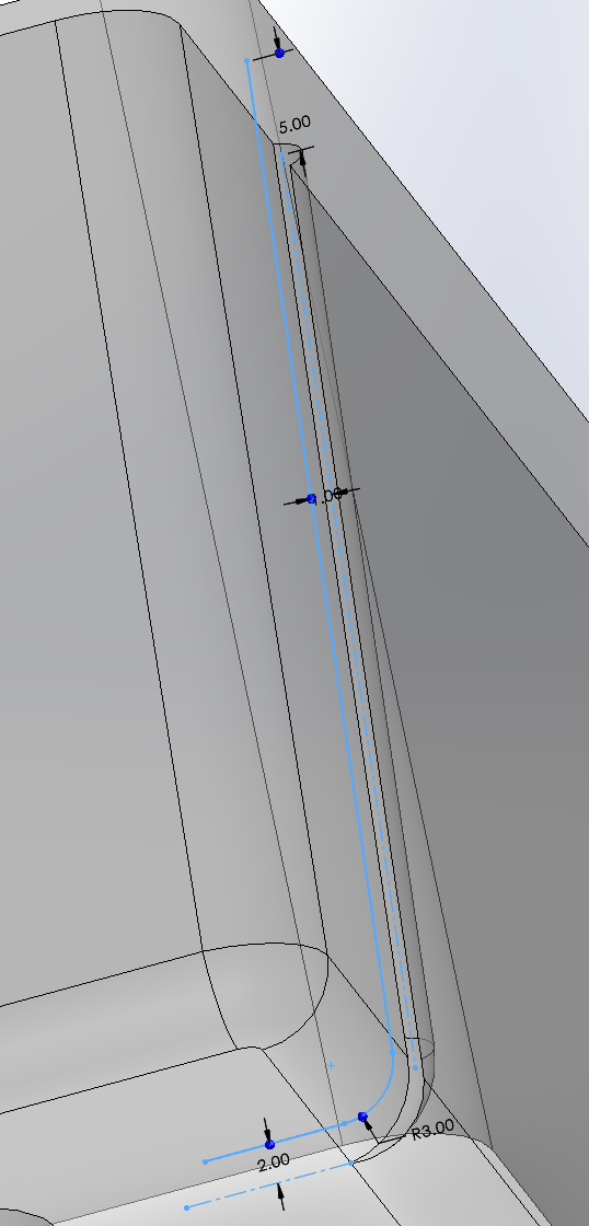
Sketch and extrude cut into the base solid, ensuring the bottom is tapered. I used specifications compatible with the design requirements for this taper, which can be defined by angle or distance from the exterior side.

After the extrusion cut, I filleted the interior cavity sides, the cavity bottom, and the tray's exterior sides to ensure smooth transitions throughout the mold.
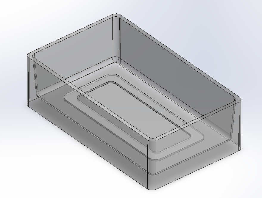
Now I drew a bottom profile which includes filleted sides on both the exterior and interior sides. This profile provides structural support for the tray and hides potential plastic defects that would be visible on a flat sheet.
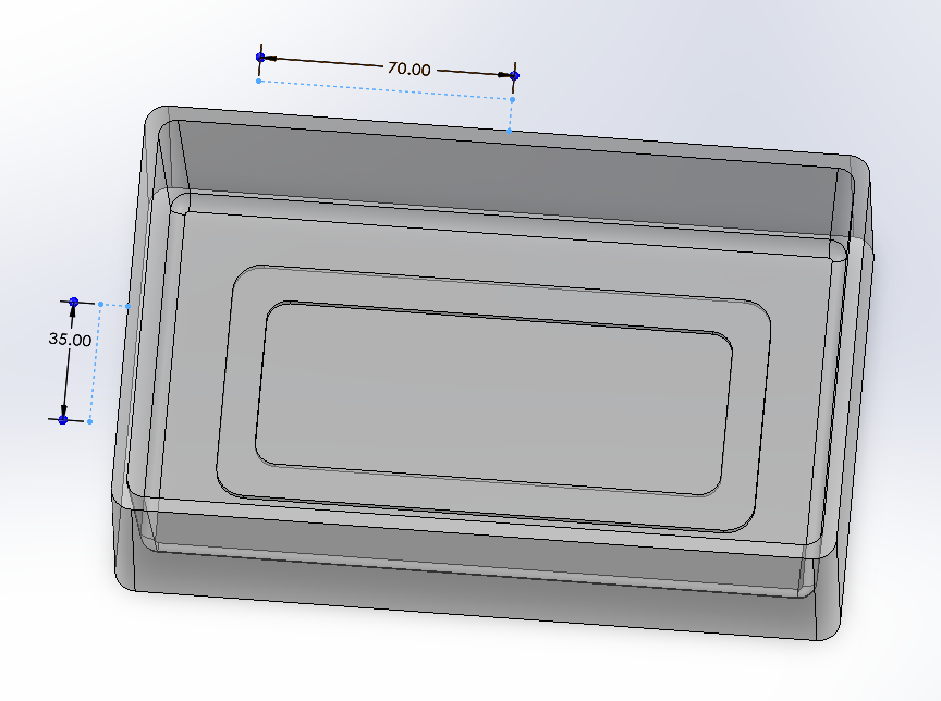
Created bones/ribs guideline sketch based on the customer's spacing requirements. For this example, we used 10mm as the base unit. We left space between the ribs and the filleted edges, settling on 70mm for the primary span. The other side measures 35mm as the project width is half the length.
With the rib sketch complete, I created the ribs themselves by extruding cuts into the solid walls. These were then multiplied and mirrored using the X and Z axis planes for symmetry.
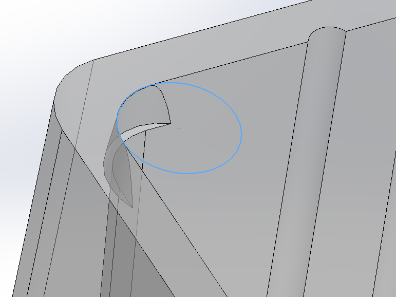
After creating the ribs, I created the corner lugs using reverse taper with the extrude cut feature, carefully positioning the circle sketch to match the fillet size.
For the final step, we used the shell feature to display what the final product would look like to clients. Note that only steps 1-9 are required to create the actual mold for production.