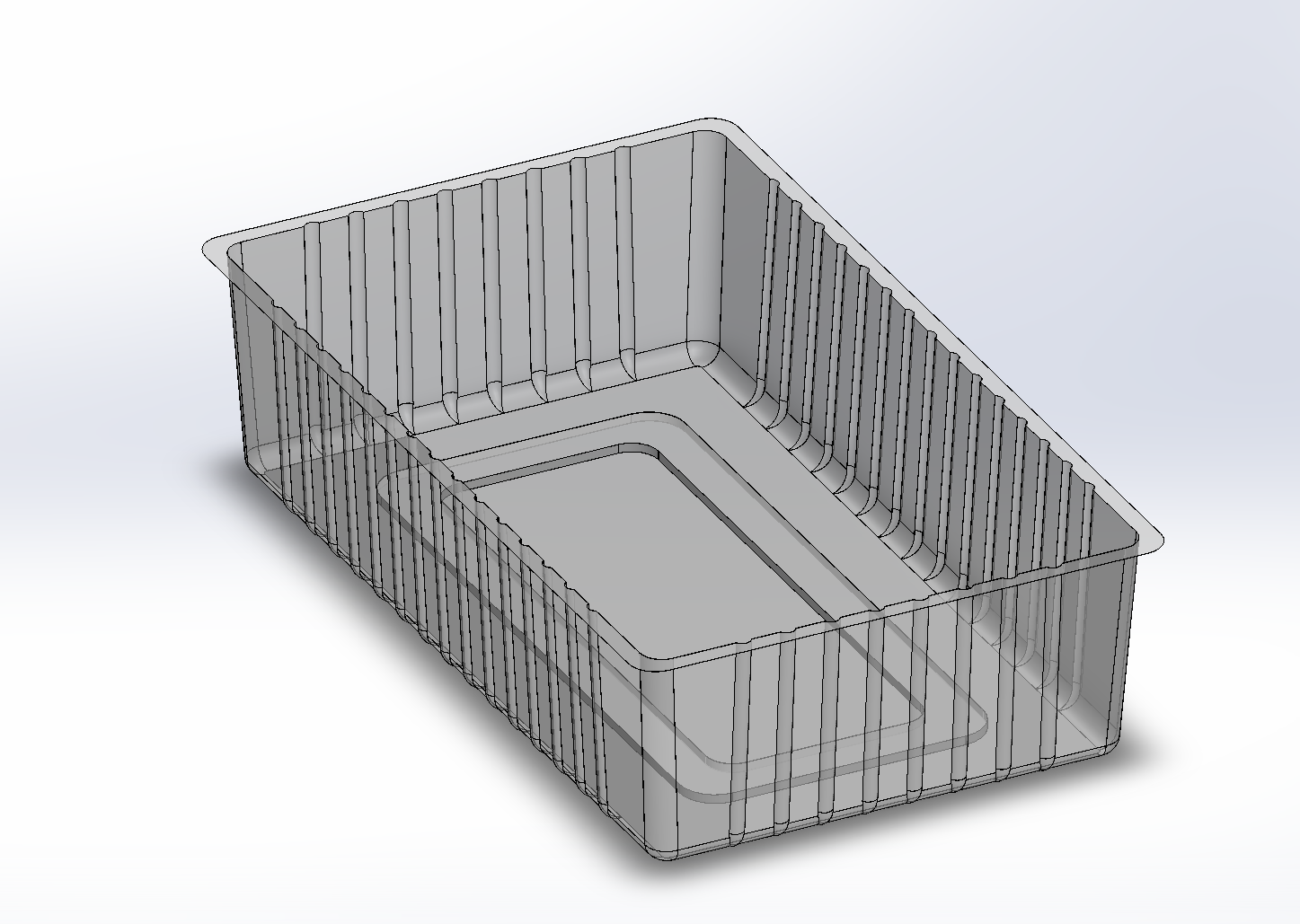
Single Cavity CAD


The first step was to create the guideline sketches. This is done to indicate the outer dimensions first. For this sample, we decided to go with 200 by 120mm. 4mm will be the distance from the inner and outer section. This is the dimensions of the top part of the cavity.

The next step was to create the real sketches based on the guidelines and extrude them downwards for a value of at least 55mm. The value 60mm was chosen because the minimum height of the cavity had to be 50mm.

After this extrude, I create a new plane 50mm below the original sketch. This plane will be used for the dimensions of the lower part of the tray.

Sketch and extrude cut into the base solid, make sure the bottom is tapered. I used specifications that would be compatible with the requirements of the design for this taper, can be angle or distance from exterior side.
Consideration/Purpose: This taper is created for the plastic trays to become stackable.


I now have to draw a bottom profile which includes filleted sides in both the exterior side and the interior side.
Consideration 3: This bottom profile is done to provide structural support for the tray and also to hide the plastic defects that may display if it was a blank sheet of plastic. The bottom of this profile does not have to be tapered as it will not touch the adjacent tray when stacking.


Create bones/ribs guideline sketch. This has to be based on multiplications of the customer’s spacing requirements, for this example, we use 10mm. However, we also need to leave some space between the ribs and the filleted edges of the cavity interior. Therefore, we came up with 70mm as it looks the best. The other side is 35mm as the width of this project is half the length.
Consideration 4: To further help with creating the ribs, we create custom planes for both the x and y axis based on the distance of the points from the guideline sketches.

Now with the sketch of the ribs done, I create the ribs themselves. We extrude cut the ribs into the solid walls and multiply and mirror them with the help of the x and z axis planes.
Consideration 5: The ribs are created because it reinforces the structure of the sidewalls. Without these ribs, the tray might crumple vertically.

After creating the ribs, I can now create the corner lugs using the reverse taper with the extrude cut feature and careful positioning of the circle sketch. It also follows the fillet size.
Consideration 6: The corner lugs are designed to prevent the trays sticking together when stacked. For this example, the lugs are 5mm in height. This means that there is a 5mm gap between the trays when stacked. This is very important as is it common for customers to request the gap for stackable trays to fit their automatic filling machines (filling with their products).

For the final step, we use the shell feature to display to the clients what the final product would look like. After all, we only need up to step 9 to create the mold for the product.